Robot Technologies
Adaptive Vibration Damping in Industrial Robots

How magnetorheological fluid dampers work and where they fit in manufacturing
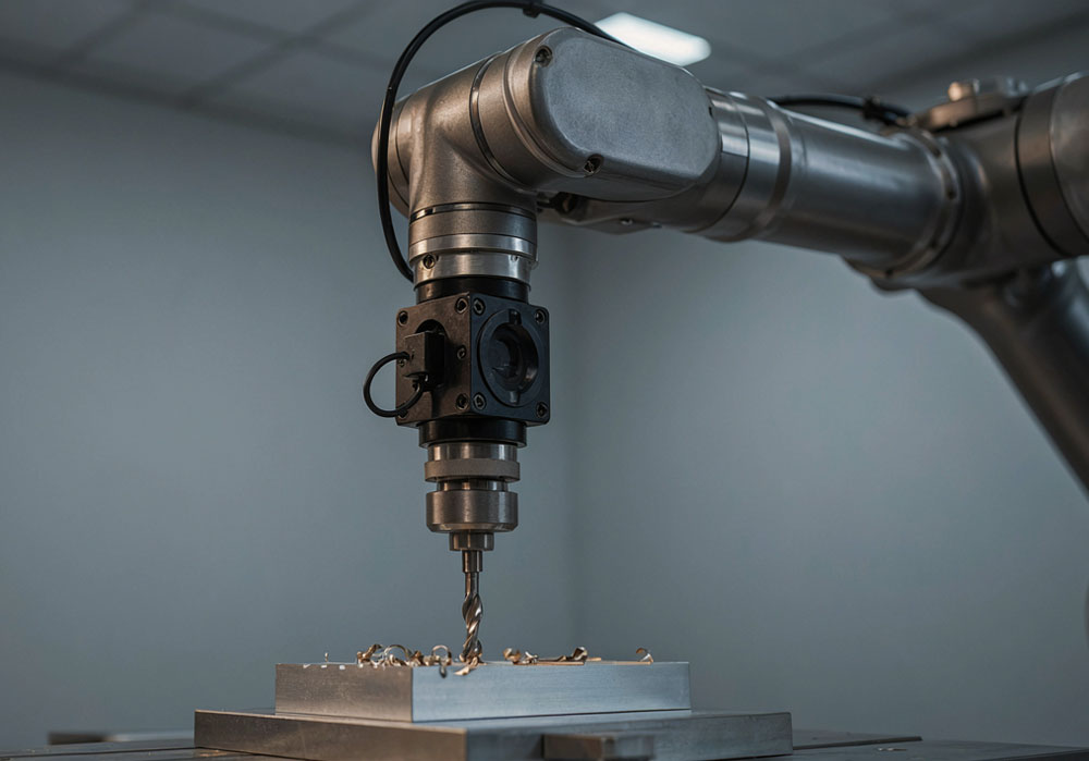
A robot can change its vibration response as the tool moves across a single workpiece. Magnetorheological fluid dampers can adapt to these changes by using coil current to vary resistance to motion. Robotic milling experiments have recorded substantial reductions in tool-tip vibration. On a production line, the value of those reductions depends on surface quality, cycle time and maintenance costs.
Why vibration depends on robot pose
A six-axis industrial robot can reach different surfaces of a large workpiece and use several tools in the same cell. That freedom of movement comes with a trade-off in machining. Cutting forces deflect the tool tip because the joints, links and tool have finite stiffness. As the arm changes pose and the direction of the cutting force shifts, so does the tool tip’s response to a given force. Cutting parameters that produce stable machining in one position can cause problems elsewhere on the same tool path. Tunç and Gönül found that the dynamic response of a moving robot can differ from its stationary response, affecting the stability limits for low-frequency chatter. [1]
Spindle imbalance, periodic forces from the rotating tool and the entry and exit of individual teeth can produce forced vibration. Chatter is a self-excited instability in the cutting process. In regenerative chatter, for example, the waviness left by one tooth changes the chip thickness encountered by the next. This changes the cutting force and the surface profile it leaves behind. Instability can also arise through coupling between the robot’s structural vibration modes. The distinction determines how to test a device that lowers vibration amplitude and how to verify whether it widens the range of stable cutting conditions. [2]
How a magnetic field changes flow resistance
A magnetorheological (MR) fluid contains magnetisable particles on the micrometre scale dispersed in a carrier liquid. When a magnetic field is applied, the particles form chain-like structures along the field. The shear stress required to disrupt these structures rises. The effect is largely reversible as the field weakens. A key engineering parameter is the field-dependent yield stress that must be exceeded for the fluid to flow. The yield-stress curve in Parker Lord’s MRF-132DG data sheet shows diminishing gains as the field strength increases. The curve represents typical properties for that specific fluid. [3]
In a linear damper, the piston forces fluid through a narrow passage. A coil generates the magnetic field that changes the pressure drop across the passage and the resistance to piston motion. A rotary joint module can shear the fluid between surfaces that move relative to each other, producing resistive torque. A third arrangement targets small relative movements by squeezing the fluid between approaching surfaces. This squeeze mode is also used in the MR foam prototype mounted near the cutting tool. [4, 5]
MR foam holds the fluid within a porous carrier. In an MR elastomer, magnetisable particles are embedded in a solid polymer matrix. An elastomer-based vibration absorber can use a magnetic field to adjust its stiffness and shift the frequency band it targets. The systems examined here use the yielding or shearing behaviour of the fluid. [4, 6]
The limits of semi-active control
A servo actuator can deliver mechanical work to a robot on command. An MR damper generates controlled resistance and dissipates mechanical energy associated with relative motion. Its coil and driver consume electricity. The release of stored elastic energy and internal friction can influence measured force, while the damper’s control authority remains limited to the range of damping forces it can produce. If both mounting points move almost together in the target vibration mode, increasing coil current will have little effect. The mounting position therefore matters as much as the current setting. [7]
Adjustable hardware can be operated in three ways. The first uses one current setting throughout the process. The second selects preset current levels according to robot pose, tool or machining recipe. The third uses acceleration, position, velocity or force measurements as feedback and updates the current during operation. A reduction in vibration at constant current establishes performance under that test condition. Demonstrating that a controller can track changing conditions requires a separate test. The control strategy and the baseline should both be reported when assessing the system’s readiness.
The fluid’s rapid response to a magnetic field is only one part of the response at the tool tip. Coil inductance, eddy currents in the magnetic circuit and mechanical force transmission all affect the total response. Strecker and colleagues found that a fast current driver did not improve the measured force response as much as expected because eddy currents in the magnetic core limited it. A test specification should therefore distinguish current rise time from damping-force rise time. [8]
Robotic milling and grinding studies
| Study and mounting position | Reported finding | Scope of the evidence |
| MR foam damper near the tool [4] | Radial vibration amplitude fell by 37–69% in KUKA KR500 milling tests | Tool-tip measurements under the tested cutting conditions |
| MR joint damper [5] | Low-frequency vibration was suppressed across several poses and cutting conditions | Effect depends on joint angles and cutting conditions |
| MR damping unit in a grinding end effector [9] | Prototype force was measured at different currents, compression speeds and displacements | Mechanical characterisation of the component |
| MR fluid absorber on the spindle housing [10] | Chatter suppression was assessed in simulation | Model result |
Li and colleagues developed a ring-shaped MR foam damper that fits around the tool holder for robotic milling. They carried out slot milling tests on a KUKA KR500 at spindle speeds of 2,000, 3,000, 4,000 and 5,000 rpm. Feed rate, depth of cut, width of cut and damper current were held constant across this series. The researchers reported a 37–69% decrease in radial vibration amplitude at the tool tip. The percentage range refers to vibration amplitude measured for a specific prototype under those test conditions. Production rate and surface roughness require separate measurements. [4]
The magnetorheological joint damper, or MRJD, adds damping at a joint that participates in the vibration mode. Mounting the device at the joint avoids placing its mass at the tool tip. The researchers tested its effect on low-frequency chatter at different robot poses and cutting parameters and investigated where it performed best as joint angles changed. For production planning, this points to evaluating robot poses and dominant vibration modes along the tool path before choosing current settings. [5]
One objective in robotic grinding is to keep contact force consistent as the tool follows the workpiece geometry. Adjustable damping in the end effector can be evaluated for its ability to reduce oscillation during contact. A 2025 study measured damping force in a prototype under different currents, compression speeds and displacements. The next stage of validation in a production cell would measure surface marks, fluctuations in contact force and cycle time per accepted part. [9]
Production cell integration and acceptance testing
The first step is to identify the source of the defect. Tool runout, fixture compliance and tool wear can produce similar symptoms in vibration measurements. Combining three-axis acceleration measurements near the tool tip with spindle speed data and measurements of the finished surface makes it easier to connect vibration to the defect. An impact hammer test can identify the dominant frequencies and directions at different robot poses. Recordings taken during cutting can then show whether those findings hold under operating conditions. [1, 2]
For a damper mounted on an end effector, centre of gravity and moment of inertia matter as much as mass. A component that improves damping in the target direction can increase the load on the robot wrist or shift another vibration mode. A joint installation requires checks on access, cable routing, changes in resistive torque and servo tracking error. In a grinding cell that uses precision force control, adding a mechanical damper may require retuning the force control loop. These requirements depend on the cell design.
Comparisons should use the same tool, workpiece, tool path and cutting parameters. Three conditions can be measured separately: no damper, damper installed with the field off, and damper installed with the field on. This separates the effects of added mass and off-state fluid resistance from the additional damping obtained by applying current. If constant current appears sufficient, a comparison with variable current under the same conditions can show whether extra sensors and software are justified.
Acceptance criteria should cover more than the peak amplitude at one frequency. Vibration in the target band can be tracked alongside surface roughness and dimensional error. Stable depth of cut matters in milling, while contact force fluctuations matter in grinding. Productivity should be assessed by material removed at the same quality threshold or cycle time per accepted part. Coil and driver power consumption, rework rates, tool life and maintenance downtime also belong in the calculation.
Durability and opportunities for industry in Türkiye
Prolonged storage can change how particles are distributed in an MR fluid. Extended cycling can also change the fluid’s response to the magnetic field. Force response should therefore be checked both on the first cycle of a shift and after the equipment reaches its operating temperature. The maintenance plan should cover leakage, seal condition, coil temperature and the damping available after power loss. Experiments that measured fluid properties after extended damper operation support checking how the response changes over the service life. [3, 11]
For teams designing robotic production cells in Türkiye, possible pilot applications include robotic deburring, grinding cast parts, trimming composite edges and light milling of large components. These are engineering proposals based on the applications discussed here. A pilot can start with an operation where the affected part, robot pose and quality loss have already been documented. Where the tool path and cutting parameters already produce stable results, the financial benefit of extra damping may be limited. Where surface defects force an operation to run at a low feed rate, the pilot can measure whether lower vibration translates into a shorter cycle or less rework.
MR dampers allow a robot’s dynamic response to be adjusted as working conditions change. Milling experiments have demonstrated the approach at the tool tip and at the joint. A production decision requires measurements across the robot’s working envelope and throughout a shift, with the effect expressed in cost per accepted part. [4, 5]
References
- Tunç, L. T. and Gönül, B. (2021). Effect of quasi-static motion on the dynamics and stability of robotic milling. CIRP Annals. Source link
- Chatter stability in robotic milling. Robotics and Computer-Integrated Manufacturing. Source link
- Parker Lord. MRF-132DG Magneto-Rheological Fluid Technical Data Sheet, DS7015. Source link
- Li, B., Su, C., Zhao, W., Song, S., Tian, W. and Liao, W. (2024). A novel method of suppressing machining vibration in robotic milling using magneto-rheological foam damper. Chinese Journal of Aeronautics, 37(12). Source link
- Low-frequency chatter suppression in robotic milling using Magnetorheological Joint Damper (MRJD). (2025). Chinese Journal of Aeronautics, 38(3). Source link
- Mode coupling chatter suppression for robotic machining using semi-active magnetorheological elastomers absorber. Mechanical Systems and Signal Processing. Source link
- Spencer, B. F., Dyke, S. J., Sain, M. K. and Carlson, J. D. (1997). Phenomenological Model for Magnetorheological Dampers. Journal of Engineering Mechanics, 123(3), 230–238. Source link
- Strecker, Z., Roupec, J., Mazůrek, I. and Klapka, M. (2015). Limiting factors of the response time of the magnetorheological damper. Source link
- Design and analysis of magnetorheological damping vibration isolation device for robotic grinding system. (2025). Journal of Advanced Mechanical Design, Systems, and Manufacturing, 19(1). Source link
- Hou, M., Shi, J. and Cao, H. (2023). Chatter suppression for robotic milling using a novel magnetorheological fluid absorber. MM Science Journal. Source link
- Material Characterization of a Magnetorheological Fluid Subjected to Long-Term Operation in Damper. Materials. Source link